
|
Archive_Proposed%20Software.pdf Size : 0.196 Kb Type : pdf |
3.0 Proposed Software Architecture
3.1 Overview
This section describes the requirements of the distinct proposed software architecture. The system we propose is designed as a collection of services, which uses the SAMS middleware to communicate with each other. These services can run on separate hardware components e.g. wearable, laptops, that are then networked together to provide the desired functionality.
3.2 Subsystems and Services
The system is divided into several subsystems, which are described in terms of their services.
3.2.1 Subsystem Decomposition
The subsystems resulting from the subsystem decomposition are:

The figure above shows the main systems are divided into subsystems, how different subsystems communicate with each other and how they work together.
SAMsSubsystem: This subsystem is responsible to
initiate other three subsystems, which AlarmSubsytem, ReportSubsystem, and
SensorSubsystem.
AlarmSubsystem: This subsystem is responsible to
respond the emergency has happen. Then give generate alarm after have notify
the emergency really occur.
ReportSubsystem: This subsystem is responsible to generate report from SAMsSubsystem information and verification.
SensorSubsystem: This subsystem is responsible to notify it real emergency occurred or just dummy for the system, and identify
the level if
emergency before the alarm will generate.
AdminstratorSubsystem: This subsystem is notified to administrator the emergency has occurred and will receive the report from ReportSubsystem.
Fire_RescueSubsystem: This subsystem is notify to Fire & Rescue Department the emergency has occurred and will receive the report
from ReportSubsystem
3.2.2 Services of the Network Subsystem
The Services of Network Subsystem can be grouped into the following three types, Communication, Location, and Service Management which maps to the three subsystems of SAMS middleware: Communication System, Location System, and Service Management System.
The communication subsystem encapsulates the functionality of communication between Services. It manages communication resources such as event channels and shared memory blocks. The communication subsystem creates Connectors when instructed to do so by the ADMINISTRATOR. A Connector manages Communication Resources at one end of a connection between one Service’s Need and another Service’s Ability. The ADMINISTRATOR can actively tell the Connector to connect to another Service, or it can tell it to passively wait for incoming connections.
The following Connector of Communication Subsystem will support two major types of data transfer services in the SAMS project; Transfer small amount of data (such as navigation information), Transfer big amount of data (such as video/audio streams, bulk data).
I. The RTPServer Connector supports the RTPServer interface, with the method RTPServerSend, which enables the sending of real time streaming data from the server’s side.
II. The RTPClient Connector supports the RTPClient interface, with the method RTPClientReceive, which enables the receiving the real time streaming data from the client’s side.
The location subsystem provides the basic functionality of locating Services. The location subsystem does not know about communication protocols, connectors, Services or Abilities. It simply deals with Offers and Requests. Offers consist of a location and a set of attributes, and Requests are predicates over these attributes. The location subsystem periodically tries to find Offers to match its Requests. The ADMINISTRATOR will creates Offers and Requests from each Service’s description and determine which sector must be observe. It maps a Service’s Abilities onto Offers, telling the location subsystem to advertise these on the network. Analogously, it maps a Service’s Needs onto Requests, which the location subsystem tries to answer. The SAMS service access the Service Location Functionality only indirectly via the description of their needs and abilities.
The direction navigator will show ways to the safe section and close the infected areas automatically with ADMINISTARTOR’s observation.
Service Management - The ADMINISTRATOR will provides the initial interface to the SAMS middleware and possesses the following features:
I. Active Service Descriptions: Internally, ADMINISTRATOR consists of Active Service Descriptions. An Active Service Description exists throughout the life cycle of a Service and represents the Service within the ADMINISTRATOR. It has a state reflecting the state of the Service. So the ADMINISTRATOR will always aware of the current system state and can take immediate actions if necessarily.
II. Coordination: The ADMINISTRATOR coordinates the other subsystems and creates Requests and Offers in the location subsystem to satisfy a Service’s Needs and to make its Abilities available to other Services. It instructs the communication subsystem to connect the Services together that the location subsystem locates. So ADMINISTRATOR can sends backup team if there is an emergency alert.
III. Starting and Stopping: ADMINISTRATOR can start and stop the security alert system manually. This is important because the system might be too sensitive and generates the emergency alarm falsely. So ADMINISTRATOR can check the actual situation and shut/stop the security alert if necessarily.
3.3 Hardware/software mapping
Based on performance considerations and client request, our target deployment platform consists of wearable BENQ products with limited resources, running Linux and windows, and laptop(s) for processing computation- intensive tasks, both running Mac OS X and Vista. Development is done on both operating systems, but mainly on Mac OS X.
Figure below show how the Hardware and Software being map in SAMs.

3.3.1 General System Performance
Due to the nature of augmented reality, SAMS aims at real-time response times concerning the information displayed for ADMINISTRATOR. For any network requests, SAMS aim is a maximum response time of one minute. However, SAMS cannot guarantee network response time, due to circumstances beyond our control like heavy network traffic.
3.4 Persistent Data Management
The persistent data will be stored (at least in the first build) in the file system. The used file types include
I. WDL files (workflow description language)
II. IETM’s, HTML and media files (for GUI)
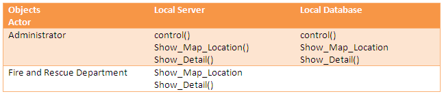
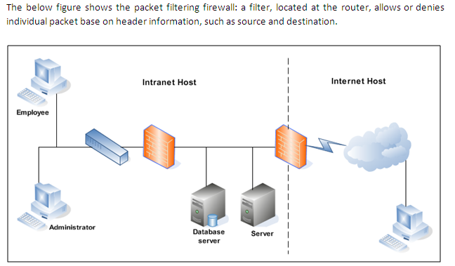
3.5 Access control and security
i) Providing Access Control
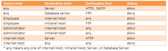
Security Alarm Monitoring System (SAMs) is application provide the directly connection between the internal server, and database server to the Fire and Rescue Department. The database will trigger the alarm input to the server, and then the server will directly trigger the alarm to notify the Fire and Rescue Department. In the intranetworking topology must have access control to control or filter every packet come in/out to the network using the configuration at the router act as firewall. Below table shows the access matrix for Security Alarm Monitoring System (SAMs).
ii) Security
Security Alarm Monitoring System (SAMs) is application focus on server, and database application, so it not must worry about the security. This system only provides authentication security base on Message Authentication Code (MAC), when to access the server and database server. This method used to prevent such unauthorized to access the critical path in the intranetworking, like server, and database server.
Message authentication code (MAC) is a short piece of information used to authenticate a message. A MAC algorithm accepts as input a secret key and an arbitrary-length message to be authenticated, and outputs a MAC (sometimes known as a tag). The MAC value protects both a message's data integrity as well as its authenticity, by allowing verifiers (who also possess the secret key) to detect any changes to the message content, and so should be called Message Authentication and Integrity Code: (MAIC).
3.6 Global software control
i) Procedure-driven control: This part is required operation wait for input, in this system the alarm will be trigger when has changes in the environment. The administrator must insert the identification before can has authorize to access the server, and database. System will analyz update the database base on the input from the image processing. The report emergency will be generate when the system has comfirm the emergency occur.
ii) Event-driven control: The alarm bell will be ringing until the sensors be activated to control situation. The alarm bell also will be turn off manually by administrator if has the dummy emergency warning. Then the Light-Emitting Diodes (LEDs) lightning at the Control Panel will keep blingking until the sensors deactivate operation.
iii) Threads: The sensors will operate when its get the input data from the system, and image processing input. The sensor will fault operate when has a confillic data as the input, like the location emergency not robustness declare. If this happen, the sensors must be manual activated by adminstrator.
3.7 Boundary condition
i) Intialization: When the server and the database start-up the system will automatically will check the all sensor are also automatically connected to the database. Then if the sensor success fully communicate, the Light-Emitting Diodes (LEDs) will lightning on the Control Panel to notify the adminstrator the sensor in good condition.
ii) Termination: When the emergency occur, the alarm will trigger then the database will update current information status, bofore the database will triger the sensors, and the send the data to the server. Then the server will send the notification to the Fire and Rescue Department.
iii) Failure: When the system failure to operate the system will directly connected to the client hot spot server and database before the main server and database recovery. This to make sure the system will always available 7 days per week, 24 hours per day.